| WIRCam Home |
| CFHT Home |
| General Information |
| News (Mar 25 2008) |
| Instrument Description |
| Publications |
| Acknowledgment Text |
| Specifications & Performance |
| Performance Summary |
| Technical Considerations |
| Instrument Throughput |
| Instrument Modification History |
| New Observing Process |
| Exposure Time Calculator |
| Queued Service Observing * |
| SkyProbe * |
| Data Preprocessing & Calibration |
| `I`iwi Preprocessing Pipeline |
| Preprocessing Queue |
| Standard Stars Zero Points |
| CFHT MetaData Products |
| Calibration Images Archive |
| `I`iwi Oral Presentations |
| Real Time Image Processing |
| Twilight Flat-Fields Status |
| Focus Sequences Status |
| Instrument Operations |
| WIRCam Cooling * |
| Cage Temperature * |
| On-sky Instrument History |
| Observing Runs |
| External Related Sites |
| Data Archiving at CADC * |
| Terapix Data Processing Center * |
| Contacts |
| Support Astronomers |
| Outreach |
| WIRCam 1st Light |
| * = External Browser Link |
| The IDL Interpretor of the WIRCam Images (`I`iwi) - Version 1.0 | ||||||||||||||||||
Table of contents:
Introduction and OverviewThe raw WIRCam images have the odometer names ??????o.fits, are coded in 16-bit unsigned integers (0-65535 - make sure to use the BZERO and CHIPBIAS keywords) and are stored as multi-extension FITS (MEF) images (1 primary header + 4 extensions). Additionnally, the MEF can be cubes or singles slices, i.e. each extension can contain one or more images (look for NAXIS3=? in the extension headers). The full mosaic and cube slices can be correctly viewed with ds9 version 4 and higher with the commands: ds9 -mosaicimage ??????o.fits, or ds9 -mosaicimage wcs ??????o.fits (correctly displays the WCS) The IDL Interpretor of WIRCam Images (`I`iwi - pronounced E-e-vee - a native hawaiian bird) preprocesses all the o.fits images and produces two sets of results: 1) the ??????p.fits images which are detrended (dark subtracted, flat fielded, etc) and are sky subtracted; 2) the ??????s.fits images which are detrended but NOT sky subtracted. This is intended so that PIs can use their own sky subtraction strategy without having to start from scratch. There is a subtle difference between PREprocessing and processing. CFHT preprocesses every single image but does NOT coadd them into a deeper stack. The stacking, so-called the processing, can be done on request by the TERAPIX team. The image processing steps needed to remove the instrument imprints are globally referred as the "detrending". In addition to the standard detrending steps usually taken (dark subtraction, flat fielding, etc), the WIRCam detectors (HAWAII-2RG) have specific imprints requiring special detrending recipes (R stands for Reference pixels, G for on-chip Guider - not the same beast as HAWAII-2 - a.k.a. WFCAM). For example, on some detectors, the guide window produces a structured cross extending all the way to the edges of the arrays. But the most important artifact plagging the WIRCam images is the different types of electronic crosstalks which produce doughnut-shaped artifacts which need to be accounted for. The next section will dwelve in all the details of the detrending recipe. To identify which version of `I`iwi was used for preprocessing, look for the keyword IIWIVER in the "Processing Pipeline" section of each FITS extension. That keyword was not put in for the beta version. Chances are the beta version was used if preprocessing was done before September 2007. It is probably wise to familiarize yourself with how WIRCam images are generated before going any further. Figure 1. Flow Chart of the Preprocessing of WIRCam images
Caption: The images are first detrended to remove all detector imprints (except the crosstalks). Then the sky is constructed using adjacent adjacent s.fits images and subtracted. Then, as a final step, the crosstalk is removed from both the finally preprocessed images (p.fits) and the detrended-only images (s.fits). Astrometry and photometry are then performed using SExtractor and are updated in the image headers. The astrometry is a simple linear solution while the photometry is based on standard stars observations (also based on 2MASS for the J,H and Ks filters). Detrending
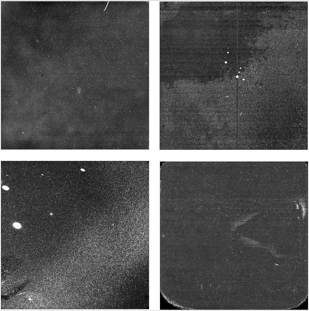
Reading the imagesThe raw images are stored as multi-extension FITS files. Each extension can be a single slice or a cube of up to 28 slices. If the keyword NAXIS3 exists, it is set to the number of slices. We prefer to use the CMPLTEXP keyword (non-standard, put by CFHT) which always exists and states the same information. The raw images are stored in 16-bit unsigned integers. This is also the output format of the processed images (p.fits and s.fits). The first step in `I`iwi is to convert 16-bit to 32-bit floats because all image processing steps are in floats. In converting to float, one must be carefull to use both the BZERO and CHIPBIAS (CFHT non-standard) extension keywords. All raw and processed WIRCam images have had an arbitrary constant value added to prevent 16-bit wrapping of negative numbers into high positive numbers when producing the CDS image (subtraction from two images). We call this constant the CHIPBIAS and we have settled its value to 7000, but it used to be 3000 earlier in the life of WIRCam (at least the first year). In addition, the very standard BZERO keyword is usually set at 32768. In IDL, for example, reading an image is as follows: raw = bzero + float(mrdfits(RAW_NAME, extension)) - chipbias Important note. A constant CHIPBIAS of 7000 is arbitrarily added to all processed WIRCam images. On sky subtracted images, this means the background level is around 7000 adu. Flagging the saturated pixelsA very first step is to identify which pixels are likely to be saturated and keep a record of them so the finally preprocessed images can have them correctly flagged to 65535. We adopt thresholds of 24000 adu (for semesters 05B and 06A - which have a low electronic gain) and 36000 adu since semester 06B (the gain was changed in August 2006). These thresholds are not as definitive as those one would set for CCD images. This is simply because WIRCam images are CDS subtraction and, depending on the sky brightness (actually the sky rate) and detector readout time, the background in the first read may be at a higher or lower level than expected. Important note. An irreversible filter is applied to the data has it is being taken at the telescope. The RAW and REF reads that go into producing a CDS image are compared to a saturation map, in the acquisition system itself. Pixels in either of the two reads having values above the map are immediately flagged as saturated and assigned the value 65535 in the CDS image that is saved. Care was taken in producing that saturation map so it represents the values at approximately 95% full well. This has the advantage of limiting the number of stars affected by black holes at the core of bright saturated objects, easying the task of our automatic acquisition software that picks guide stars. Non-linearity correctionNear IR detectors are notoriously non-linear in their flux response (typically 5% non-linear before saturation compared to less than 1% at saturation for CCDs). The non-linearity is intrinsic to the arrays (the charges accumulate in a capacitor-like device for which the capacitance is affected by the number of charges) as opposed to CCDs for which non-linearity comes from the non-perfect behavior of amplifiers. The problem of the non-linearity correction (NLC) is compounded by the fact that only CDS images are saved for WIRCam, not the two single reads (learn more about the image readout scheme). This means that an iterative approach is required to apply the NLC. We characterized the non-linearity of each of the four arrays by observing the warm floor of the observatory when WIRCam is off the telescope and taking images of different exposure times (typically from 5 seconds to 90 seconds) to yield fluxes of 4000 ADU to 55000 ADU per pixel. We frequently (every 15 minutes for 7 minutes) took short exposures (5 to 7 seconds) to establish a baseline and make sure there was no intrinsic flux variation. For this calibration, we exceptionnally save both reads as well as the CDS image. That characterization started in August 2006.... Impact on the zero points. Before/After August 2006.... For the moment, here is an example of the WIRCam Non Linearity Curves. Reference pixels subtractionHAWAII-2RG detectors have an effective surface of 2040x2040 sensitive pixels. A 4-pixel wide border is used as reference to correct for relatively slow bias drifts, first seen during WIRCam commissionning as column to column DC offsets on a scale of several tens of columns. Here, it is assumed that each column is approximately constant and that any drift is seen as a level change between columns. In other words, we correct only the presence of vertical bands. Only the rows of 4 reference pixels on top and at the bottom of images are used, those on the left and on the right are not used. First, we correct the reference pixels themselves because a small DC level slope is seen from line 0 to line 3 and from line 2047 to line 2044 (most probably due to capacitive coupling effects). So, each of those 8 lines has its median subtracted from it. Then, we consider the 4 reference pixels on top and at the bottom of each column. We consider they follow any DC change that affects the whole column. The idea is to subtract the DC level seen on those 8 reference pixels from the 2040 data pixels of the corresponding column. We construct a 2048x8 matrix of reference pixels that we median along the vertical axis to obtain a 2048x1 reference line (that median of 8 reference pixels is to reduce noise in the measurement). Then, to further reduce noise and spurious effects, we smooth the 2048x1 line with a boxchar of 9. Then we subtract the corresponding scalar value for each data column (e.g. column 5 = column 5 minus 5th index of reference line). Here is the IDL code. We pass imraw, the original image, to the function: ;Set the lines to be used as reference pixels, those at the top and bottom of ;the image. line = [0,1,2,3,2044,2045,2046,2047] med = fltarr(n_elements(line)) im = imraw ;Try to correct the small slope seen in the reference pixels themselves, i.e. ;from line 0 to 3 and from 2047 to 2044 by subtracting the median horizontal ;value from itself. reflines = fltarr(2048,n_elements(line)) for i=0, n_elements(line)-1 do begin ;Determine offset med[i] = median(im[*,line[i]]) ;Apply offset so all columns have a median of zero reflines[*,i] = float(im[*,line[i]]) - med[i] endfor ;Now, for each column, use the median of the 8 reference pixels available. ;Crunch 8 lines into 1. This is a vector of 2048 reference columns. averagecolumn = median(reflines,dimension=2) ;Smooth that column with box of 9. This is to prevent introducing noise but ;it also means that column to column variations on shorter timescales can not ;be corrected for. box = 9 averagecolumn = smooth(averagecolumn,box) ;Subtract the average, smoothed column from each data column for i=4,2043 do begin im[*,i] = imraw[*,i] - averagecolumn endfor return, im Dark subtractionThe dark current of the WIRCam detectors is generally low (less than 1 e-/sec). The cryostat is regulated to within one thousandth of a degree at about 80 K. So the dark current is thought to be very stable and varies linearly with integration time (figure ?). Instead of using up one filter position to have an aluminum blank for dark acquisition, we simply cross two science filters of different bandpasses (one in each of the two filter wheels), for example LowOH1 and H2. This has proven to yield exactly the same dark level as a pure blank. Figure ?. Master darks of different exposure times
Several structures are seen in darks:
In `I`iwi, dark subtraction is done for each slice by choosing the closest (in time) processed dark cube of the same exposure time. All except the persistence effects subtract well when a dark of the correct exposure time is chosen. A processed dark cube consists in a median of generally 15 darks taken sequentially (usually only 7 for 240sec or longer exposure times). Prior to doing the median of 15 images, each raw image is corrected for the common noise pattern (that's an electronic noise pattern common to all the 32 amplifiers -- because pixels are read in parallel -- and is constructed by the same method as that to construct the median amplifier for the crosstalk correction). A note on master darks. In the future, we plan on constructing a master dark valid for each run, one for each exposure time. Starting with semester 07B, we are systematically taking darks every morning (darks were taken manually and not as frequently before that). Flat fieldingWe are using dome flats obtained at the beginning of each observing run on the observatory dome illuminated with a tungsten lamp. We obtain a cube of 15 raw flats with the dome light turned on and subtract the 15 raw flats of the same exposure time with the light turned off. This ensures any instrumental thermal component is removed. We typically use 5-6 second exposure times for wide band filters and up to 30 second exposure times for narrow band filters and target fluxes of about 10000 adu on lamp-on flats. Here is how dome flats are processed:
Flat fields show mostly a radially increasing flux level and, fortunately, no high spatial frequency fringes. The pixel to pixel quantum efficieciency variations are of the order of a few percents. A very important note on flats and photometry. The `I`iwi convention is to treat each detector entirely separately. This means that the flat fielding step does NOT remove detector to detector quantum efficiency differences. The median background value of the processed dome flat is 1 for each of it's four detectors. In other words, the same star observed with the four detectors will yield different flux measurements. The relative quantum efficiency differences are instead being absorbed in the quoted zero-point found in each extension header of the processed images (s.fits and p.fits). More details in the photometry section. This convention has the advantages of 1) not changing the electronic gain values and therefore the relative photon statistics, 2) ***there were more fundamental reasons I forget. An other important note on illumination correction. No illumination correction is made in 'I`iwi. The change of pixel scale is small (less than 1% in the corners) and the photometry error that it introduces is much smaller than the current absolute photometry uncertainty (of 4-5%). Preliminary photometric measurements using twilight instead of dome flat fields indicate that dome and twilight flat fields are consistent to within 0.5-1.0%. Nevertheless, twilight flat fields are obtained on a regular basis and will probably be used in the next version of `I`iwi. Bad pixels masking`I`iwi uses the bad pixel mask constructed by Chi-Hung Yan (Academia Sinica - Institute of Astronomy and Astrophysics - ASIAA). He developped a method to construct bad pixel masks from darks and dome flats aided with a ds9 interface to do a second pass manual inspection - see Chi-Hung's method. The bad pixel mask has 1 for good pixels and the float Not-a-Number (NaN) value for bad pixels. Guide window maskingOn-chip guiding unfortunately has side effects on the science images. These artifacts depend on the DSP code used in clocking the science and guide pixels and a lot of effort was spent to optimize the code and minimize the unwanted artifacts. This means the side effects description and the detectors afflicted have changed between observing runs, even within a run. That complicates their removal during post processing. Figure ? shows an example of the cross centered on the guide window that extends across the whole detector. Since semester 06B, the bottom two arrays are free of guide window artifacts, only the upper two arrays are afflicted. Figure ?. Example of the guide window artifact on a fully preprocessed image
The guide window size has changed over the life of the instrument and, unfortunately, the corresponding header keywords have not always been correctly populated. The headers have been correct Note. A guide window is always read out but put in a predefined bad pixel region for unguided science exposures. Science calibration images like darks and flats are always obtained with the guide window clocked in order to always be in the same hardware setup. There are Figure ?. The two different types of guide window artifact suppression
Sky Subtraction
Intro to show sky movies etc... Identifying adjacent imagesSky construction requires the use of at least 3 (ideally 5) adjacent observations taken through the same filter at different dither positions. The detrended images are usually normalized to 1, sources are masked and a median is taken for each pixel. Best sky subtraction results are obtained when using images obtained close in time and space. So, for each image, a different set of neighboring images needs to be selected. Background level measurementThe sky background level is estimated on detrended images by using a simple median on each detector. To normalize the mosaic to a flux of 1, the relative quantum efficiency of each detector is taken into account.
 EXPTIME (sec)             SKY LEVEL (adu/sec)                CORRECTED FOR QE              MEDIAN      NORMALIZED
           All        1        2        3        4        1        2        3        4         All             All
        30.000    70.77    62.18    67.34    67.55    66.91    66.94    67.00    66.99       66.96         1.00874
        30.000    71.69    63.08    68.17    68.34    67.78    67.90    67.83    67.77       67.81         1.02142
        30.000    70.72    61.69    66.89    67.41    66.87    66.40    66.55    66.85       66.70         1.00479
        30.000    69.78    61.26    66.44    66.71    65.98    65.94    66.11    66.15       66.04         0.99488
        30.000    69.85    61.50    66.59    66.69    66.05    66.20    66.25    66.14       66.17         0.99679
        30.000    70.09    61.46    66.30    66.64    66.27    66.16    65.96    66.08       66.12         0.99606
        30.000    69.90    61.28    66.43    66.77    66.09    65.96    66.10    66.21       66.09         0.99566
        30.000    68.94    60.52    65.47    66.14    65.19    65.14    65.14    65.59       65.17         0.98166
Source maskingFor sky construction purposes, a copy of each detrended image is made. On that copy, all positive sources are masked (i.e. put to Not-A-Number - NaNs). To identify which pixels have to be masked, the pixels with a value of zero in the "checkimage" are used. Here is the parameters used when calling SExtractor: -DETECT_THRESH 1.5 -ANALYSIS_THRESH 1.5 -DETECT_MINAREA 4 -FILTER_NAME gauss_3.0_7x7.conv -STARNNW_NAME default.nnw -WEIGHT_TYPE NONE -CHECKIMAGE_TYPE OBJECTS -CHECKIMAGE_NAME checkimagename.fits -BACK_SIZE 64 -INTERP_TYPE ALL -BACK_FILTERSIZE 1 The wings of stellar sources (under the 1.5 sigma threshold) can bias the sky construction and produce dark rings after sky subtraction. To prevent this, the idea is to enlarge each masked star to make sure no wing signal creeps in. The fastest way to do this is to apply smoothing using a box of 5x5 (the smooth command in IDL). Sky construction - standardSky construction - for noddingSky subtractionConstraints and pifallsCross-talk RemovalIntroductionUntil March 2008, WIRCam was affected by three types of cross-talks. We liberally named them, the "Negative", "Positive" and "Edge" cross-talks. Here are detailed information and examples on the cross-talk effects. Positive Cross-talkNothing is done to remove this cross-talk. It is confined to the 8 amplifiers of an affected viedo board. Negative Cross-talkThis is the most important source of cross-talk. We basically subtract a median amp from each of the amplifiers. The median amp is constructed by slicing all 32 amps from a detector to create a cube of 2048x64x32 pixels (from an image where sources are masked) then simply taking the median. Edge Cross-talkThe edge cross-talk is suppressed during the medamp subtraction that removes the negative cross-talk. No need for further subtraction. AstrometryIntroductionThe goal of the astrometry solution at CFHT is to be within an error of about 1 arc second and this goal is almost always achieved. For the sake of simplicity, of robustness and because there was no FITS standard to express non-linear terms, the `I`iwi WCS solution is purely linear (assumes a constant scale). The following figure shows that WIRCam has a field distortion of about 1% in the corner of the mosaic. Figure x. WIRCam Field Distortion as Determined by Scamp
Knowing the geometry of the detectors, a first fit using all 2MASS stars found on the whole mosaic is performed. Then, provided enough stars are found, the WCS of each detector is refined individually. The RMS scatter of the resulting WCS solution is generally about 0.3-0.8 arc second. Full Mosaic Linear SolutionThe full mosaic approach makes use of the known geometry as determined by the Terapix team who produced a wircam.ahead file. `I`iwi uses this geometry to project into sky coordinates (expressed in degrees with the field center being at 0,0) the sources found by Sextractor. It fits a rotation as well as d_alpha, d_delta offsets. It then matches stars to the 2MASS catalogue. This method is robust (even for sparse fields) because it uses all sources found on the mosaic. But the detector geometry is not exact and it is not rare to see larger than 2-3 arc second discrepancies for stars in the corners of arrays. Detector by Detector Refinement Using IMWCSStarting with the list of matched stars obtained in the full mosaic solution, this method operates on individual detectors to refine the WCS solution. `I`iwi calls the IMWCS software in the WCSTools package (D. Mink, Harvard). This generally yields a better than 0.5 arc second rms solution. In rare cases, only the full mosaic solution converges and is kept. To know which method was used for each extension of the FITS file, look at the WCS_ORIG keyword in the "Processing Pipeline" section. IMWCS-linear means that the detector by detector refinement method using IMWCS worked and was kept. The quality of the fit is given in MATCHRMS, the number of stars used to initiate the fit is WCSNREF and the number of stars kept in the fit is WCSMATCH. If WCS_ORIG='MOSAIC-linear' then only the full mosaic solution could converge in which case MATCHRMS, WCSMATCH, WCSNREF and more keywords are missing. PhotometryIntroductionThe star flux is obtained using SExtractor and the FLUX_BEST is used. Arguably, this is NOT the best output photometry to use but for other reasons (an unidentified bug in SExtractor when using weight maps and thresholds different than 0) it was used rather than FLUX_AUTO (which IS probably better). No aperture correction is done on the pipeline side. We use the Sextractor values directly. Determining the zero point depends on the filter used. For narrow-band filters (basically all filters except J, H and Ks), we adopt the zero points as determined from standard star observations. The problem is there are no published standard star photomeries in the narrow bands so we use three of the four CALSPEC spectrophotometric standards (GD71, GD153 and G191B2B) which have well modeled near IR fluxes. The modeled magnitude is obtained by convoluting the filter response curves with the model spectra using a sotware developped and tested by S. Arnouts. Then: ZP_measured = mag_modeled +2.5*alog10(stars.flux) -2.5*alog10(stars.exptime) and the zero point thus measured is stored as PHOT_C0 in each FITS extension header of the s.fits and p.fits files. This WIRCam Zero Points page details the values used in the pipeline with curves for each filter and the adopted zero point offsets between detectors. For J, H and Ks, we also use the 2MASS measured values for all 2MASS stars found on each detector. These measurements are done on each actual slice of a cube, on a detector by detector basis. We apply: ZP_measured = mag2mass +2.5*alog10(stars.flux) -2.5*alog10(stars.exptime) and simply take the median of all stars (bright and faint - a weighted average would be more appropriate indeed for `I`iwi version 2). The zero point thus measured is stored as FOTC_?? in each FITS extension header of the s.fits and p.fits files (?? represents the slice number in the cube). No color term is yet included in the pipeline. Difference in Sensitivity Between Detectors - No Correction DoneA very important note about how the different detector sensitivities is handled in `I`iwi. There are two possible conventions: 1) Normalize the flux of each individual detector to a common-to-all-detectors zero point, generally done after flat fielding ; 2) Make no normalization and simply have different zero points for each detector but write the zero point in the FITS extension header. The second convention is adopted for `I`iwi. This means that on the finally preprocessed images, stars of the same magnitude placed on the four arrays will have different flux counts. The zero point is found in each FITS extension under keyword PHOT_C0 (as determined from standard stars) or keyword FOTC_?? (as determined from 2MASS stars in the field, ?? represents the slice in the cube starting with 01). The main reason for doing so with WIRCam is to preserve key hardware constants like electronic gain and saturation values which would be changed if we were to normalize all detectors to a common zero point. Note for Megacam users, the other convention is use for Megacam. Elixir normalizes all the detectors to a common zero point. For stacking purposes, one therefore needs to scale the flux of each detector appropriately. With Scamp (from E. Bertin) one needs to have the argument MAGZERO_KEY set to PHOT_C0 or FOTC_?? and use a post May 2007 version of scamp (a bug - that argument was not handled properly before). Important Header KeywordsIntroductionThe WIRCam FITS files are multi extension files (MEF) with a primary header and 4 extension headers. `I`iwi updates and edits the extension headers but not much is done with the primary header as processing is mostly on a per detector basis. The important keywordsThere are several sections in the extension headers:
|