|
The CFHT-Gemini Weather Tower
Control System (Weather Tower System) is a joint venture between the
Canada-France-Hawaii Telescope Corporation and the Gemini 8-Meter
Telescope Project. The system is designed to collect the weather
data from the CFHT tower mounted sensors, transmit data to the CFHT
dome and provide weather data for the Gemini Telescope.
This portion of the manual id dedicated to information associated
with the collection of data from the tower sensors, transmission to the
CFHT dome as well as providing the weather data to the CFHT Data
Logger. The tower sensors include measurements of wind
speed, wind direction, ground level relative humidity and
air temperature. This data is read by an Allen Bradley modular
unit and transmitted via fiber optic to the CFHT dome. A second
Allen Bradley unit receives the transmitted data nd manipulates it for
displays and the CFHT Data Logger (data-logger).

Simple
block diagram of system. Drawing is not to
scale.
|
- Schematic
Diagrams:
- Tower electronics
- Control room electronics
- Software - Allen Bradley PLC programs:
- Data Sheets
(pdf files):
The Weather Tower Control
Junction Box is mounted at the tower approximately 6 feet off the
ground.
 Weather Tower Control Junction Box
|
The junction box contains the necessary electronics to
collect and transmit the data from the sensors at the tower to the CFHT
observatory building.
The inside of the junction box can be seen below.
|
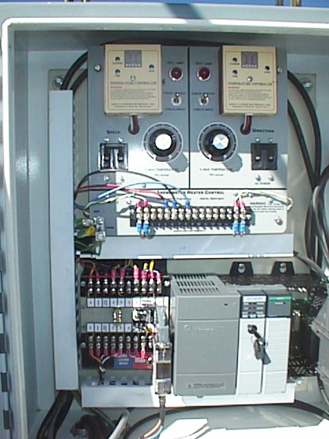
Inside the Weather Tower Control Junction
Box
Top:
Anemometer/Vane Heater Control
Btm-Lft: Terminal Board Electronics
Btm-Rht: Allen Bradley Modular Unit
Between AB Unit and terminal board (Silver Object) RS232 to Fiber
Converter.
|
- Allen Bradley Unit:
- The Allen Bradley unit collects, manipulate and
drive the data collected from the tower sensors. The unit
consists of several modules mounted in their proprietary rack.
- One rack is mounted at the base of the tower in the
tower junction box and the other is mounted in CFHT's control
room.
|
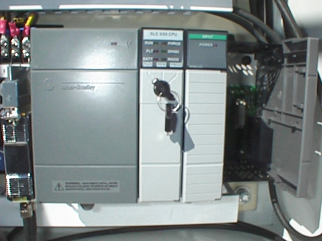
Allen Bradley unit mounted in Tower
Junction Box.
L-R: Power Supply, SLC5/03 processor, 1746-NI4 Analog Input Module
Key Switch normally switched to the left "Run" position. Switched
to "REM" for remote programming.
Telebyte Tech RS232 to fiber converter mounted to left of Allen
Bradley unit.
|
- The terminal
board contains electronics used to
interface the wind speed and direction signals to the Allen Bradley
Analog
Input Module. Also, 24
volt reference sent to RH/Temp sensor
passes through this board on the very right side. RH/Temp signals
coming back
from their sensors pass through this board on their way to the Allen
Bradley
Analog Input Module. Finally, not
pictured but mounted at this location is the power switch used to turn
power on
and off to the Allen Bradley unit.
|
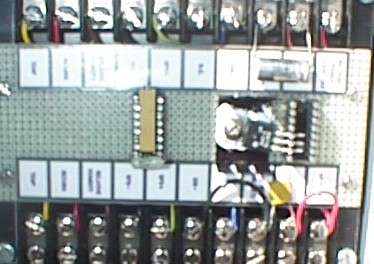
L-R Components on board.
5K potentiometer and 10K 1% resistor used for wind
speed calibration.
Regulator takes 24Vdc and creates +5Vdc reference for wind direction
(wind direction is a 0-5K potentiometer).
Terminal connections at top go out to sensors. Terminal
connections at bottom are wire to Allen Bradley unit.
|
- The
electronic controls for the heaters used to
prevent the anemometer and vane from icing in severe freezing storms is
mounted
inside top of the junction box. This
panel is divided into two parts. The two
parts are identical controls for both
the anemometer and vane. There is a
breaker to turn power on and off. The
knob is used to set the controlled percent of maximum heat. 70% is normal. The
toggle switch works in conjunction with
the red indicator light. When switched
to the “input” position, the light indicates the presence of input AC
power. When switched up to the “output”
position, the light is indicating relative power to the heaters
themselves.
|
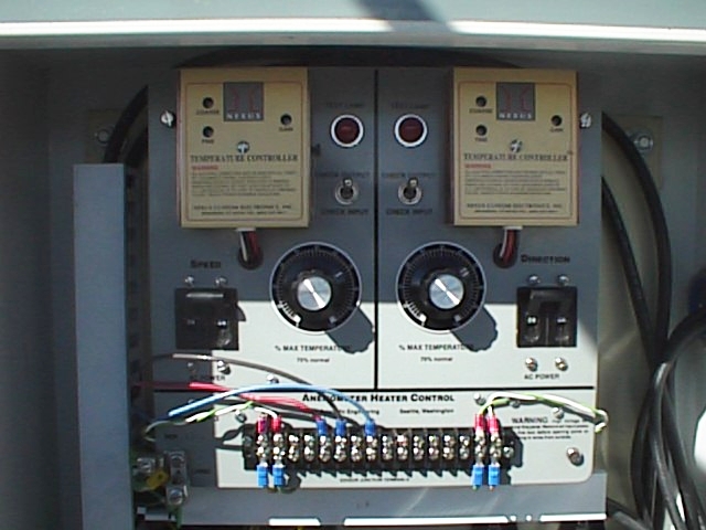
Anemometer/Vane Heater Controls:
Dials set to 70% sets heat. Toggle switch
monitoring (Red Indicator) to input
AC power or power to heaters. Grn/Whit wires
are heat sense lines coming back from
heater. AC In and AC Out to heaters are
connected in back of panel for safety.
|
|
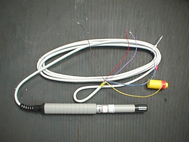
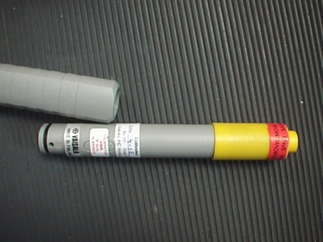
Vaisala HMP45A Relative
Humidity/Temperature
sensor:
Top photo is of sensor prior to installation into radiation shield
Bottom photo is of sensor removed from head. This allows easy
replacement of the sensor.
|
- Telebyte Technology, Inc Fiber Optic
Converter:
The RS-232 data is transmitted from one Allen Bradley unit
at the tower to the CFHT dome via fiber optic link. <><>This
conversion is done via Telebyte
Technology’s 271F/ST converter.
- The data
enters the CFHT Observatory via pair of
fiber optic which is laid in conduit underground. The
conduit is connected to a junction box
(JBW2) located on the wall in the main stair well of the building. In this junction box, the data is
converted
from fiber to RS232 and goes up to the fourth floor control room into
another
junction box (JBW3) mounted on the wall in back of the control console. From there, the data leaves the junction
box
and goes to the second Allen Bradley unit mounted close by.
|
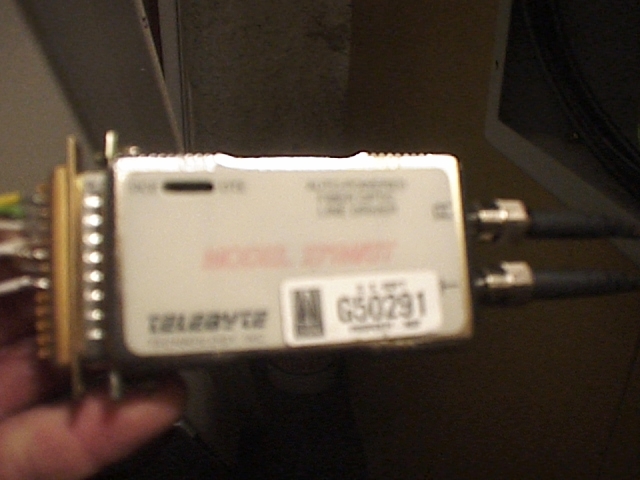
Telebyte Tech Inc. RS232 to fiber
converter (Obs Bldg).
Mounted in junction box at base of main stair well to left
of door. Notice fiber entering unit from right side with data
from tower.
DB25 connector takes serial data (2, 3, 7) and puts on
terminal block in junction box.
|

|
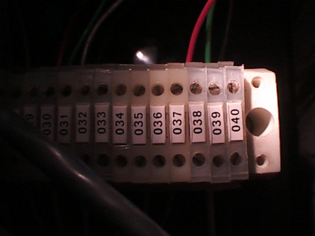
Close up of serial communications wire hook
up in ground floor junction box.
Yellow, green, brown are pins 2, 3, 7 respectively
of DB25 connector.
.These wires correspond to wires 38, 39, 40 in the junction box.
|
- The data is
taken from the junction box mounted
in the back of the control room and wired directly to the RS232 port of
the
Allen Bradley unit. The software in
the
control room Allen Bradley unit receives the data and separately scales
analog
outputs to drive the appropriate gauges or data logger lines.

|
Serial hook up in junction box in
back of telescope control room.
Red, Green, Black correspond to 2, 3, 7 respectively.
Control Room Allen Bradley
Unit:
L-R Power supply, SLC-5/03 Processor,
two 1746-NO4V 4 channel analog output modules,
1746-NIO4V Analog 2 input, 2 output module.
First 1746-NO4V module used to drive data logger.
Second 1746-NO4V module used to drive control room gauges.
Last analog module in far right slot is used for CFHT dome RH/Temp
measurement (not yet used).
|
|
 Weather Tower Documentation


