|
| MegaPrime/MegaCam Home |
| CFHT Home |
| General Information |
| Instrument Description |
| Press Release April 8, 2003 |
| Publications |
| Acknowledgment Text |
| Specifications & Performance |
| Quick Performance Summary |
| General Summary |
| Technical Considerations |
| Off-field bright stars immunity |
| Shutter ballistics |
| Baffling & pinhole mask |
| On-sky Instrument History |
| Observing Runs |
| Observing Statistics |
| Observing Statistics II |
| Upgrades & Problems |
| Zeropoint History |
| New Observing Process |
| Exposure Time Calculator |
| Mapping Stars & Pointings |
| Queued Service Observing |
| QSO PH2 |
| SkyProbe |
| Data Preprocessing & Calibration |
| Elixir System Information |
| Raw Data Description |
| CFHT Data Preprocessing |
| CFHT Data Calibration |
| CFHT MetaData Products |
| Raw & Elixir FITS headers |
| Elixir Releases History |
| Elixir Real-Time |
| Elixir RT Field Guide |
| Elixir RT Status |
| Flat-Fields Status |
| Standards Status |
| Instrument Operations |
| Cooling Status |
| Cryostat Status |
| External Related Sites |
| Data Archiving at CADC |
| Data Processing at Terapix |
| Contacts |
| Support Astronomer |
| Baffling: pinhole mask and optical obstruction |
|
The MegaPrime baffleMegaPrime is equipped with a light baffle (Figure 1) meant to stop stray light from outside the optical beam. Without the baffle, MegaCam "sees" the entire caisson central including its bright reflective parts (hand rails), as well as sides of the equatorial fork (painted bright yellow). The light baffle was installed one year after first light to reduce the stray light contamination. It is made of aluminum and its rigidity has been tested prior to its installation on MegaPrime (it attaches at the bottom of the wide-field corrector). It however needed to be tested when mounted on the telescope to ensure that it does not cause some vignetting at extreme telescope angles due to mechanical flexure. The conclusion of this study making use of a pinhole mask, is that while the extreme corners do suffer from a bit of vignetting (5% maximum) there are no measurable *variable* vignetting caused by the MegaPrime light baffle (or/and the wide-field corrector internal light baffling) depending on the position of the telescope on the sky. This guarantees that MegaCam's photometry is consistent across the whole sky from a photon gathering point of view.
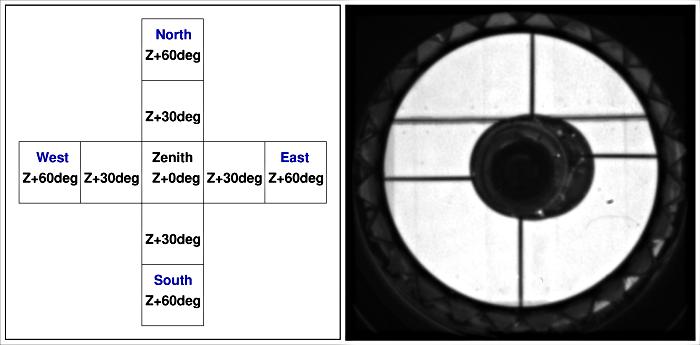
Pinhole descriptionThe pinhole mask was designed to obtain two non-overlapping images of an image hole per CCD. It was obtained with the CFHT's laser-cutting machine (LAMA) giving highly accurate holes diameter and spacing. The mask was then mounted in a standard MegaCam filter holder. When installed in the beam, the mask is only a couple of inches away from the focal plane. The Figure 2 presents two versions of the same image: the high contrast version on the left shows that the great majority of the light comes from the mirror but there are inevitable contaminations from the sides of the wide-field corrector lenses ring holder in particular (the dim rings). The low contrast version of the image (right) shows however that no light source compares to what reflects off the primary mirror.
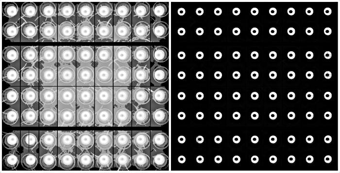
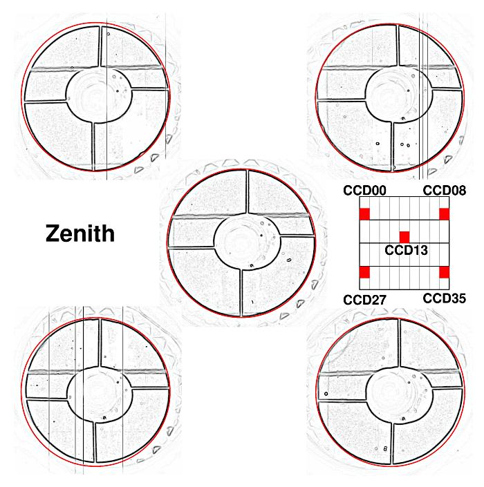
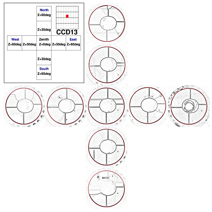
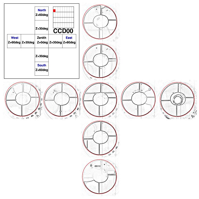
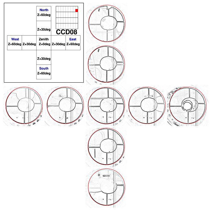
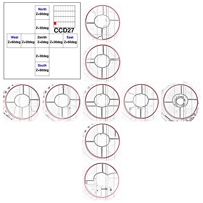
Vignetting across the field of viewThe pinhole mask creates soft images and it is difficult to measure precisely the position of the primary mirror image's edge. A simple approach is to run the images through an edge algorithm detection, followed by some unsharp masking. The result is much easier to grasp visually. Because of various features on the dome reflecting on the mirror, like a crane or rails, it is not trivial to run an automatic detection algorithm, hence the following study is based essentially on visual control.Figure 4 shows the pinhole image on 5 different positions of the mosaic (CCDs: 00, 08, 13, 27, 35) for the image taken at zenith. It is obvious here that there is indeed some vignetting in the corners versus the center. The red circle which encircles the "light" border (the limit of the primary mirror) defined by the black circle, matches the central position, and is the same for the four other positions. If the dark circle is smaller than the red circle, this means vignetting is present. This vignetting effect on the photometry is however easily corrected by the combination of the flat-field and the photometric flat-field component. Note that the vignetting does not exceed 5% (precisely measured with surface difference in this case) in the most extreme bottom left corner (CCD27).
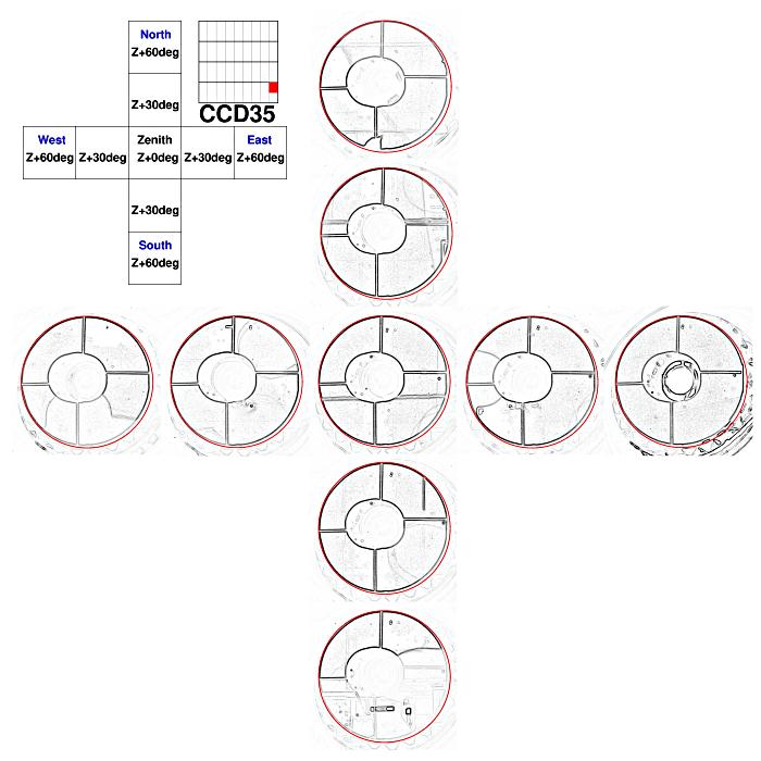
Vignetting versus telescope positionThe most important point of it all is if the vignetting is changing with the telescope position: this would be disastrous for the photometry! Figure 3 (left) shows the 9 positions in which pinhole images were taken. Note that 60 degrees from zenith is almost 10 degrees more than the most extreme angle CFHT goes to for science observations. The following figures (5, 6, 7, and 8) demonstrate that for a given location on the mosaic, the vignetting does not depend on the telescope position (all this within the limitations set by the use of the pinhole mask). Nothing jumps out at a level higher than a fraction of a percent for the corners at the extreme angles (where in such case the photometry gets limited by atmospheric effects).
|