|
|
|
MegaCam Data Elixir Pre-Processing
|
Table of contents:
1. Overview of the Elixir pre-processing
1.1 Scope of the data pre-processing
The scope of the Elixir MegaCam data pre-processing is to provide the user
with an image which has been fully corrected for the instrumental signature
across the whole mosaic. This means:
- The photometry must be uniform across the field of view: a given star
or galaxy has to have the same flux in the final image no matter where it falls
on the focal plane.
- The image must look flat in the case of deep sky exposure (not some
star forming region which has intrinsically some large scale diffuse structures).
- The bad pixels and the overscan regions must be set to the 0 ADU value.
- The initial dynamic of the data must be preserved (no truncation).
- If possible, all CCDs in the mosaic are astrometrically and photometrically calibrated
(this part is discussed in the "CFHT Data Calibration" section of this site).
The input raw data are 16 bits unsigned data ranging from 0 to 65535 ADUs. Elixir
pre-processing generates an output also in 16 bits unsigned but with the
BSCALE and BZERO parameters judiciously used to properly represent the initial
dynamic of the data on a 16 bits range even after the data have been scaled up
during the flat-fielding process. There is no reason indeed to go to 32 bits as
the noise in the signal (read noise or sky photon noise) still largely
dominates the error budget versus the bit truncation error.
1.2 Pre-processing chronology
The pre-processing is handled by a collection of Elixir tools and in a concern
of making the processing as fast as possible, some operations are done all at once
and can be grouped as follows, while the following 3 listed steps are exclusive. All
data will go at least through Step 1.
- Step 1: Camera/optics additive & multiplicative components and bad pixels masking.
- Step 2: Fringes correction (for the i' and z' band data only).
- Step 3: Modes correction (all filters).
At most, the frames are read in and written out three times in the case of the i' and z'
frames though the fringing correction applies only to exposures longer than 30 seconds.
The sky modes correction is not applied for exposures shorter than 30 seconds also.
Note that the FITS keywords added during these various steps keep track of the
filenames coming in and going out (except for the Modes at this moment).
The Elixir code knows how to handle a CCD image with two amplifiers and
the output FITS keywords reflect these operations.
1.3 FITS headers
The whole set of keywords related to the data pre-processing is included
here (keywords aren't presented in that exact order actually, for clarity
the Elixir general info has been moved to the top here) and is discussed
by section in the following chapters.
  COMMENT --------------- Elixir Analysis ---------------
  COMMENT Elixir: processing performed @ CFHT, version 2.0
  COMMENT Elixir: version: 2.0
  COMMENT Elixir: processing date: 2003-11-05T14:56:45
  COMMENT Elixir: website: http://www.cfht.hawaii.edu/Instruments/Elixir
  COMMENT Elixir: email: elixir@cfht.hawaii.edu
  COMMENT Elixir: team: Eugene Magnier & Jean-Charles Cuillandre
  DATEPROC= '2003-11-05T14:56:45' / Processing Date
  EL_SYS  = '2.0               ' / Elixir System Version
  HISTORY imred: FLIPS ver 3.0 - Elixir by CFHT - Wed Nov 5 2003 - 14:31:58
  COMMENT imred: Elixir / Flips2 flatten.flips
  HISTORY imred: Input image:  712672o.fits[ccd13]
  HISTORY imred: Output image: 712672p13.det
  HISTORY imred: Camera offset correction with overscan level subtraction
  HISTORY imred: Overscan A amp computed from [1:32,1:4644]      = 1234 ADU
  HISTORY imred: Overscan B amp computed from [2081:2112,1:4644] = 1217 ADU
  HISTORY imred: Overscan model: 1D median Y axis vector in bias section
  HISTORY imred: Mask bad pixels: * 2003A.mask.0.36.00.fits[ccd13]
  HISTORY imred: Bias structures: - 03Am06.bias.0.36.00.fits[ccd13] (mode A_amp=0
  HISTORY imred: Flat-fielding: * 1.0 / 03Am06.flat.i.36.02.fits[ccd13]
  HISTORY imred: Normalized flat-field (ref. scaling factor= 1.1)
  HISTORY imred: Preserving dynamic: stretching 65K ADU range by 1.063 (BSCALe)
  IMRED_DT= 'FLIPS ver 3.0 - Elixir by CFHT - Wed Nov 5 2003 - 14:31:58' / Date
  IMRED_IF= '712672o.fits[ccd13]' / Input file to process by imred
  IMRED_OF= '712672p13.det'      / Output file resulting from the process by imred
  IMRED_OP= 'MASK_BP + OVERSCAN + BIAS + FLAT-FIELD' / Operation(s)
  IMRED_MK= '2003A.mask.0.36.00.fits[ccd13]' / Mask of bad pixels (0/1) input file
  IMRED_OV= '1DYMODEL_OVERSCAN'  / Type of overscan level correction
  IMRED_BS= '03Am06.bias.0.36.00.fits[ccd13]' / Bias frame input file
  IMRED_FF= '03Am06.flat.i.36.02.fits[ccd13]' / Flat-field frame input file
  IMRED_NF=                    T / Normalized flat-field
  IMRED_SF=          1.063288212 / Output file dynamic stretching factor (BSCALe)
  HISTORY imcombred: FLIPS ver 3.0 - Elixir by CFHT - Wed Nov 5 2003 - 14:37:29
  COMMENT imcombred: Elixir Defringing
  HISTORY imcombred: Output image: 712672p13.def (16 bits)
  HISTORY imcombred: Fringing correction: scaled difference of 2 images
  HISTORY imcombred: Thresholding inputs from -100.00 to 130000.00 ADUs
  HISTORY imcombred: Fringe image correction: mode offsetting + fringe rescaling
  HISTORY imcombred: 712672p13.det 1960 1.000
  HISTORY imcombred: 03Am06.fringe.i.36.01.fits[ccd13] 2860 3.255
  IMCMB_DT= 'FLIPS ver 3.0 - Elixir by CFHT - Wed Nov 5 2003 - 14:37:29' / Date
  IMCMB_AL= 'SD      '           / CCD or SIGMA clipping, Scaled or Weighted Diff.
  IMCMB_CA= 'SCALED_DIFFERENCE'  / Combining algorithm on final stack
  IMCMB_FT= 'DEFRINGE_SCIENCE'   / Stacked frame type
  IMCMB_OP= 'MODE_OFFSETING + FRINGE_RESCALING' / Input operations
  IMCMB_NI=                    2 / Number of input files
  IMCMB_DA=                    F / Dual amplifier A,B (IMCMB_XX list format)
  IMCMB_IF= 'NAME BIAS MODE SCALING' / Input file parameters
  IMCMB_00= '712672p13.det 0 1960 1.000' / Input file stats
  IMCMB_01= '03Am06.fringe.i.36.01.fits[ccd13] 0 2860 3.255' / Input file stats
  COMMENT  SVD Mode map applied using Elixir demodemap 2.0.0
  COMMENT  SVD Mode file: 2003A-mode-v2.modes.i.36.01.fits
  MODE_IN =                      / SVD Mode file
  MODE_N  =                    8 / Number of SVD Modes
  MODE_0  =     -1540.2098900000 / Amplitude of SVD Mode 0
  MODE_1  =        81.1006085000 / Amplitude of SVD Mode 1
  MODE_2  =         0.0000000000 / Amplitude of SVD Mode 2
  MODE_3  =         0.0000000000 / Amplitude of SVD Mode 3
  MODE_4  =         0.0000000000 / Amplitude of SVD Mode 4
  MODE_5  =         0.0000000000 / Amplitude of SVD Mode 5
  MODE_6  =         0.0000000000 / Amplitude of SVD Mode 6
  MODE_7  =         0.0000000000 / Amplitude of SVD Mode 7
|
2. Bad pixels mask
2.1 Features covered by the bad pixels mask
The features set to the 0 ADU level by the masking procedure are described in
the section 3.4 of "Raw Data Description" of this site. The overscan areas
as described in the section 1.2 of "Raw Data Description" are also set to
0 ADU after the information for the level correction has been extracted.
The masking regions are rectangles only of any size down to 1x1 pixel.
The complete set of regions coordinates for all 36 CCDs in the mosaic
can be found here. A region is
defined as "X0 Y0 X1 Y1" where X0,Y0 is the lower left corner of the
box and X1,Y1 its top right corner.
2.2 FITS headers
The following FITS headers are associated to the bad pixels masking:
 HISTORY imred: Mask bad pixels: * 2003A.mask.0.36.00.fits[ccd13]
 IMRED_OP= 'MASK_BP + OVERSCAN + BIAS + FLAT-FIELD' / Operation(s)
 IMRED_MK= '2003A.mask.0.36.00.fits[ccd13]' / Mask of bad pixels (0/1) input file
|
3. Camera additive components
3.1 Overscan
The overscan presents a gradient along the Y axis and must be modeled in
consequence: a set of 40 superpixels sampling the overscan (median estimator)
which is then interpolated back to the native resolution and subtracted to
the regions of the CCD relevant to that amplifier. The final median level of the
overscan in any location ends up at 0 ADU.
The FITS data encoding process (BSCALE & BZERO) is adjusted such that data
can go as low as -100 ADUs to the cost of truncating 100 ADUs off the
upper side of the dynamic. This allows for negative values on very short
exposures (low background) after the overscan has been subtracted.
3.2 Bias
A bias subtraction is necessary to remove the pixel ringing at the beginning
of each line. A master bias frame is built for each observing run with a
collection of up to 20 to 30 individual frames.
3.3 Dark current
The dark current is low enough to be neglected.
3.4 FITS headers for the camera additive components
   HISTORY imred: Camera offset correction with overscan level subtraction
   HISTORY imred: Overscan A amp computed from [1:32,1:4644]      = 1234 ADU
   HISTORY imred: Overscan B amp computed from [2081:2112,1:4644] = 1217 ADU
   HISTORY imred: Overscan model: 1D median Y axis vector in bias section
   HISTORY imred: Mask bad pixels: * 2003A.mask.0.36.00.fits[ccd13]
   HISTORY imred: Bias structures: - 03Am06.bias.0.36.00.fits[ccd13] (mode A_amp=0
   IMRED_OP= 'MASK_BP + OVERSCAN + BIAS + FLAT-FIELD' / Operation(s)
   IMRED_OV= '1DYMODEL_OVERSCAN'  / Type of overscan level correction
   IMRED_BS= '03Am06.bias.0.36.00.fits[ccd13]' / Bias frame input file
|
4. Camera and optics multiplicative components
4.1 Gain and quantum efficiency
In order to obtain a uniform zero point across the mosaic, all CCDs must be
converted to a similar gain times quantum efficiency. This is easily achieved
by dividing the mosaic image with a flat-field mosaic image which CCDs have
been normalized in respect of CCD00 to maintain the ratio in gain and
quantum efficiency. The result of the division is a flat looking mosaic image.
4.2 Optics
The optics transmission is not uniform across the various lenses of the
wide-field corrector, the filter and the cryostat window. A flat-field
operation will correct these slight variations of the sensitivity across
the field of view.
4.3 Pixel scale
The MegaPrime optics present a distortion from center to edge which causes the
apparent pixel scale to change. This has an impact on the measured flux per
pixel of an object if it falls at the center of the mosaic or at the edge,
and it must be accounted for. This is the role of the photometric superflat.
4.4 Filter bandwidth
As the beam bents towards the edges of the field, the apparent bandwidth of
the filter becomes larger and just like the pixel scale effect, it affects
the flux of an object whether it falls at the center of the mosaic or at the edge,
and it must be accounted for. This is the role of the photometric superflat.
4.5 How the flat-field is built
Elixir uses twilight flat-fields because they are the best to flatten
efficiently the nighttime science data and because they can be built at
a very high signal to noise ratio level such that the flat-fielding operation
does not inject noise in the processed image (but actually reduces it by improving
the pixel-to-pixel intrinsic quantum efficiency variation). They however
have flaws, mainly a scattered light term component which, fortunately, can
be corrected with the photometric superflat.
A photometric superflat is built by measuring the flux of thousands of stars
across the mosaic on a frame processed with a plain twilight flat, as they are
moved in various location. The principle is to build a correction map to apply
to the flat-field such that in the end each star has the same flux no matter
where it is observed on the mosaic. This correction map is then convolved
into the twilight flat and in consequence all the effects mentioned above
in this section are corrected at once during the single flat-fielding step!
4.6 FITS headers for the multiplicative components: the flat-fielding
   HISTORY imred: Flat-fielding: * 1.0 / 03Am06.flat.i.36.02.fits[ccd13]
   HISTORY imred: Normalized flat-field (ref. scaling factor= 1.1)
   HISTORY imred: Preserving dynamic: stretching 65K ADU range by 1.063 (BSCALe)
   IMRED_OP= 'MASK_BP + OVERSCAN + BIAS + FLAT-FIELD' / Operation(s)
   IMRED_FF= '03Am06.flat.i.36.02.fits[ccd13]' / Flat-field frame input file
   IMRED_NF=                    T / Normalized flat-field
   IMRED_SF=          1.063288212 / Output file dynamic stretching factor (BSCALe)
4.6 CCD specifications evolution and FITS headers updates
When the raw image is processed, its intrinsic properties are affected
and the FITS keywords originally describing the behavior of the data
have to be updated.
The following set of keywords proposes the value before "<" and after
">" the flattening step. Note that the fact that the preprocessing
is supposed to remove the amplifier signature for a given CCD, the
"AMPLIST" keyword is set to the "A" amplifier only.
The other keywords (MAXLIN, MAXLINA, MAXLINB, SATURATE,
GAIN, GAINA, GAINB)
are scaled in respect of the multiplicative factor applied during the
flat-fielding.
At that point, the keywords (MAXLIN, SATURATE and GAIN
shall be enough to qualify a given CCD.
  < AMPLIST = 'A B     '           / List of amplifiers for this CCD
  ---
  > AMPLIST = 'A       '           / Data are now as if CCD read from A amp

  < MAXLIN  =                65535 / Level at 1% linearity departure (ADU) = Average
  < MAXLINA =                65535 / Level at 1% linearity departure (ADU) A amp
  < MAXLINB =                65535 / Level at 1% linearity departure (ADU) B amp
  < SATURATE=                65535 / Saturation value (ADU)
  < GAIN    =               1.6900 / Converting gain (e-/ADU) = Average [A,B] amps
  < GAINA   =               1.6600 / Converting gain of A amplifier (e-/ADU)
  < GAINB   =               1.7200 / Converting gain of B amplifier (e-/ADU)
  ---
  > MAXLIN  =                69582 / Level at 1% linearity departure (ADU)
  > MAXLINA =                69582 / Level at 1% linearity departure (ADU) - A amp
  > MAXLINB =                69582 / Level at 1% linearity departure (ADU) - B amp
  > SATURATE=                69582 / Pixel saturation level (ADU)
  > GAIN    =               1.5894 / Converting gain (e-/ADU)
  > GAINA   =               1.5612 / Converting gain of A amplifier (e-/ADU)
  > GAINB   =               1.6176 / Converting gain of B amplifier (e-/ADU)

  < BZERO   =              32768.0 / Zero factor
  < BSCALE  =                  1.0 / Scale factor
  ---
  > BZERO   =     34634.4400000000 / Zero factor
  > BSCALE  =         1.0600000000 / Scale factor
New keywords are also added to provide statistics on the flux level
of the processed images. Those are purely informative keywords not
intended to be used in further steps of image processing.
  IMMODE  =                 1929 / Imaging area mode
  FLATSCAL=          0.000000000 / Mosaic flat-field scaling factor
  IMMODEA =                 1957 / Imaging area mode for A amplifier
  IMMODEB =                 1957 / Imaging area mode for B amplifier
|
5. Sky and background additive components
5.1 Fringes
The current recipe for the fringe correction in i' and z' is based on a linear
scaling and subtraction of a master fringe pattern to the science frame.
The master fringe pattern is built by scaling to a same level a large set of
fringed images after having subtracted their continuum. For both operations,
robust statistics are achieved by computing a single scaling factor for
a mosaic image (36 CCDs, hence 36 measurements from which the median is
taken as the best estimate for the whole image). This technique achieves
a residual of less than a 0.1% for the best cases and 1% for the worse cases.
Indeed, it was noticed that for certain images, second order terms (most
likely an airmass dependency) play an important role. A more refined
method to bring down the residual to less than 0.1% in all cases is under study.
5.2 Modes correction
The photometric superflat introduces a bow at the center of image, the result
of more scattered light in that area most likely. To achieve a flat-looking
image for deep sky exposures (as it should be) a recipe based on principal
component analysis allows for the correction of the various structures found
in the flattened/defringed images.
Note that the modes correction only affects the global look of the image,
and the photometry is not affected on the small scales as it consists in the
subtraction of a large map. Note that this is not appropriate for the surface brightness
measurements of extended structures - Elixir does not have yet a flag to
skip that part for the PIs prefering not to have that last step affecting
their data.
The modes maps are built using the largest possible collection of images
to ensure that only real trends get modeled. At this moment Elixir
is limited to the correction of the first two modes due to the lack
of statistics (these two modes proved to be real as we could see a
clear improvement of the data quality after correction).
The sky background modes correction is not applied on exposures shorter
than 30 seconds as the signal is not high enough to derive solid statistics
since the sky contribution to the image signal is fairly low.
5.3 FITS headers for the sky additive components
Fringe correction:
   HISTORY imcombred: FLIPS ver 3.0 - Elixir by CFHT - Wed Nov 5 2003 - 14:37:29
   COMMENT imcombred: Elixir Defringing
   HISTORY imcombred: Output image: 712672p13.def (16 bits)
   HISTORY imcombred: Fringing correction: scaled difference of 2 images
   HISTORY imcombred: Thresholding inputs from -100.00 to 130000.00 ADUs
   HISTORY imcombred: Fringe image correction: mode offsetting + fringe rescaling
   HISTORY imcombred: 712672p13.det 1960 1.000
   HISTORY imcombred: 03Am06.fringe.i.36.01.fits[ccd13] 2860 3.255
   IMCMB_DT= 'FLIPS ver 3.0 - Elixir by CFHT - Wed Nov 5 2003 - 14:37:29' / Date
   IMCMB_AL= 'SD      '           / CCD or SIGMA clipping, Scaled or Weighted Diff.
   IMCMB_CA= 'SCALED_DIFFERENCE'  / Combining algorithm on final stack
   IMCMB_FT= 'DEFRINGE_SCIENCE'   / Stacked frame type
   IMCMB_OP= 'MODE_OFFSETING + FRINGE_RESCALING' / Input operations
   IMCMB_NI=                    2 / Number of input files
   IMCMB_DA=                    F / Dual amplifier A,B (IMCMB_XX list format)
   IMCMB_IF= 'NAME BIAS MODE SCALING' / Input file parameters
   IMCMB_00= '712672p13.det 0 1960 1.000' / Input file stats
   IMCMB_01= '03Am06.fringe.i.36.01.fits[ccd13] 0 2860 3.255' / Input file stats
Modes correction:
   COMMENT  SVD Mode map applied using Elixir demodemap 2.0.0
   COMMENT  SVD Mode file: 2003A-mode-v2.modes.i.36.01.fits
   MODE_IN =                      / SVD Mode file
   MODE_N  =                    8 / Number of SVD Modes
   MODE_0  =     -1540.2098900000 / Amplitude of SVD Mode 0
   MODE_1  =        81.1006085000 / Amplitude of SVD Mode 1
   MODE_2  =         0.0000000000 / Amplitude of SVD Mode 2
   MODE_3  =         0.0000000000 / Amplitude of SVD Mode 3
   MODE_4  =         0.0000000000 / Amplitude of SVD Mode 4
   MODE_5  =         0.0000000000 / Amplitude of SVD Mode 5
   MODE_6  =         0.0000000000 / Amplitude of SVD Mode 6
   MODE_7  =         0.0000000000 / Amplitude of SVD Mode 7
|
6. File naming conventions
6.1 Science detrended (pre-processed) frames
The Elixir filenames are simply defined using acronyms and version numbers.
The raw CCD file is read directly from the MEF file can be recognized with the
following syntax: "712672o.fits[ccd13]". The detrending process (overscan, bias,
mask and flat-fielding) outputs such image as "712672p13.det". The defringing
process then turns the image into "712672p13.def" and at last the modes correction
causes the final file name "712672p13.fits". For files requiring only the detrending
step, the output file name would be directly "712672p13.fits".
When all 36 CCDs have been processed, they all get packed into a single MEF file.
6.2 Master detrending frames
The master detrending frames have self explaining names, such as "03Am06.bias.0.36.00.fits"
which stands for a MEF file composed of 36 extensions (CCDs), which is a bias frame for
the Elixir run ID "03Am06", and its version number is "00". "03Am06.flat.i.36.02.fits"
stands for the version "02" of a 36 extensions i' band flat-field MEF file for the Elixir
run ID "03Am06".
The higher the version number is, the most recent, and relevant, the frame is for the
data processing.
|
7. Illustration of the process with real data
|
The following example follows an exposure (704897o taken in June 2003) through
the 3 steps of Elixir pre-processing. The large bowed structures seen on the
flattened and defringed images is 10% of the sky background while the final
residual on the modes corrected image (final image made available) is only
1.5%.

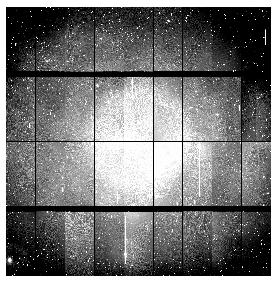
Figure 1. Raw data on the left, flattened data on the right.


Figure 1. Defringed data on the left, modes corrected image on the right.
|
|
|
