

The Redeye cameras are equipped with a set of filters that are commonly used
in infrared astronomy. This
filter set will surely grow with time as demands for more filters for
specific programs are made. Observers
are reminded that filter selection in the near infrared is complicated by the
strong atmospheric absorption
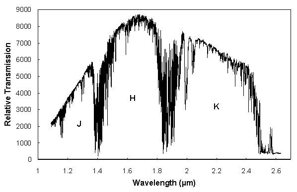
that occurs around 1.4, 1.9, and 2.5 m. Figure 4.1
is a scan made of the full moon with CFHT's FTS
(provided by Jean-Pierre Maillard) and clearly shows the atmospheric windows
that filters must work
within in order to deliver reasonably stable photometry. The atmospheric
absorption lines that define
these windows are variable in strength from night to night and depend
primarily on the amount of water
vapor over Mauna Kea at the time of observations, though CO2 is an important
absorber at these
wavelengths as well (see Chapter 5).

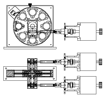
Each Redeye camera contains two filter wheels, mounted along the same rotation axis and separated by 7 mm. The filter wheel subassemblies are shown in Figure 4.2. The notches on the outer circumference of the wheel are used for positional encoding. Each wheel contains 8 filter cells for a total of 16 in each camera. Figure 4.3 illustrates one of these wheels in detail. Note that each filter cell is deep enough to hold a filter that is 6 mm thick. Filters are clamped in place via 3 small copper tabs that surround each filter cell. The inside diameter of each cell is 1.05", with a clear diameter for light to pass through of 0.90".


Visitor filters can be easily mounted in these wheels by members of the CFHT technical staff if observers send their filters to CFHT at least 2 weeks prior to their run. Bear in mind that the cameras require ~24 hours to complete one thermal cycle, hence last minute filter installations will be very difficult. Since the wheels are coaxial, one cell must be left empty in each wheel at all times so light can pass through the cartridge assembly. Also, a single cell must be left with a blank-off for dark frames. This leaves 13 cells available for filters in each camera, which should be enough to cope with most observing sessions. In the event of long blocks of Redeye time, requiring a multitude of visitor filters, compromises may have to be made so a camera does not have to be cycled in the middle of a block of observations.
On the outside of each camera is a large red tag, identifying the filters and cold stop currently loaded in the camera, when they were installed, and by whom. Observers are encouraged to check this tag before their run begins to make sure the filters they need for their run have been installed and correspond to the filter list displayed on the Redeye/Pegasus session.
The filter wheels are controlled remotely via a Redeye/Pegasus data acquisition session (see Chapter 6). Under normal circumstances users need only select a filter via a button in Pegasus and the summit computer will make sure that the correct filter is automatically rotated into place, while placing the other wheel in an open position. In the event of a catastrophic failure of this motorized filter control, it is possible to manually rotate filters into the proper positions. This is accomplished by first disconnecting the two cables leading to each of the filter wheel stepper motors (to remove all drive current), then disconnecting the large 32 pin cable leading to the "utility" socket on the outside of the camera dewar. Next, attach the small filter wheel indicator box (located in the CCD lab with the other Redeye accessories) and plug that into the utility socket on the camera. Turn on the box with the double throw switch. When a filter is in position, an LED will light up. The "A" wheel is that closest to the camera's window. Rotate the filter wheels by turning the black knob on the end of the stepper motors, until 3 positions close together are detected (see the notch encoding in Figures 4.2 and 4.3). The middle notch of these 3 is the "home" position, or filter #1, which is always left open in both the A and B wheels. Rotating the knobs clockwise corresponds to increasing filter numbers on the red tag posted on the dewar. Once home position for each wheel is located, it is possible to rotate either wheel into the desired position with this LED indicator box.
Once again, this procedure should only be done in the case of a catastrophic failure of the remote filter wheel controller in the middle of the night, so that all is not lost because of problems with the filter wheels. Also, note that by removing the original cable from the 32 pin "utility" socket, all control over the detector's temperature is lost, meaning it will drop to 77 K and remain there until the camera loses its LN2 reserve. If the detector temperature was more the a few degrees above this value before you pulled the utility cable, a new set of darks should be taken as a precaution against drift in the array's dark current.
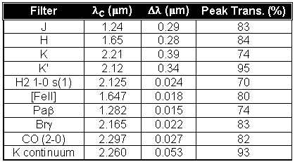
At the time of Redeye's commissioning, there are 10 filters available for general use in each camera. All of these filters were manufactured by Barr, hence are essentially identical to the filters in use at the UH 88" and the IRTF. This includes the K' filter, which is shifted slightly to shorter wavelengths than the K filter, thereby reducing thermal background flux significantly. Table 4.1 lists these filters, along with their basic properties.

Additional specifications for all of the stock filters include:
In the following pages are transmission curves for all of the Redeye stock
filters. These curves were made
with the IRTF's lab IR spectrometer in Honolulu. As new filters are added to
the standard stock of Redeye
filters, this set of transmission curves will be updated. It is important to
note that this spectrometer has a
blue cut-off of 1.25 m, hence the bluest stock
filters are not fully scanned. The spectrometer also is a bit
noisy at the blue end of spectra, making absolute transmission values near
~1.3
m unreliable. If
necessary, cold transmission curves made by the manufacturer of the bluest
filters are available upon request from CFHT.
The filters are split into two groups, namely those dedicated to the
narrow field Redeye camera,
and those dedicated to the wide field camera. Accordingly, each transmission
curve is labeled either "wide
camera" or "narrow camera". In all cases, a "cold" curve corresponds to the
filter at 77 K, while a
"warm" curve corresponds to 295 K. For the narrow band filters in particular,
this change in temperature
shifts central wavelengths a significant fraction of the central band passes.
Throughputs are also, in
general, increased by ~10% when the filters are cold. For each filter a full
1.2 - 5.0 m scan is shown to
reveal any leaks in the filters. Since the filters were designed to work with
a 1 - 2.5
m array, the leaks
that are seen in all of the narrow band filters beyond ~3
m are not important. Finally, digital
versions of these transmission curves, in the form of ASCII text files, are
available via anonymous ftp to
ftp.cfht.hawaii.edu, in the same manner as this entire manual (see Chapter 1).


